
Lesson 6 : Ribbon system for IK/FK
We'll take a look at how to make a rebound system with a good overlay to get more deformation.
This system lets you create and simulate rig layers on your characters. This will give your characters a wider range of deformation possibilities. From something very rigid to something very soft and flaccid
Table of Contents
1. Logical explanation
2. Setting up the rig ribbon system
3. Node graph connection
4. Implementation system for ik/fk
5. How to skin
6. Sources
1. Logical explanation
A ribbon system, what is it? It's a system that allows us to have layers of rigging that enable both animators and riggers to manipulate an element, such as an arm. With ribbons, we can deform the shape of the arm, either rounding it or correcting aspects that may not look aesthetically pleasing.
Alternatively, this system allows for multiple levels of detail in your rig: a global level that deforms an object, and subsequent levels to more precisely modify your object.
Here's an example using an arm and any object.


This system involves constraining joints onto a surface or a curve, and then skinning that curve with other joints. These joints can themselves be driven by something else, creating layers of deformation in sequence.
It's an system that proves useful in many cases, whether for facial rigging (if you're not using BlendShapes), for limbs, objects, or virtually anything else. This system can be likened somewhat to a lattice, but traditional lattices can be cumbersome to set up and heavy in some situations. In contrast, this system is highly adaptable.
Personally, I prefer using surfaces over curves because curves can be restrictive, especially when dealing with rotations, whereas surfaces deform more easily.
Joints constrained on the surface

Joints deforming the surface

This system effectively allows you to create all sorts of deformations, whether smooth or sharp.
SMOOTH SHARP
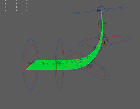

2. Setting up the rig ribbon system
To put this system into practice, we will use a baseball bat model a simple model that will help us understand how to create this system effectively.

To create this system, first place a surface at the level of our baseball bat so that it covers the entire 3D model. It should extend slightly beyond the edges, but not too much.

Next, you need to decide how many controllers you want to use to deform this surface.
The number of controllers is crucial because it determines how we will rebuild the surface. There should be 1 span per controller. If there are too few or too many controllers, it will result in deformations that are not optimal. When we subsequently skin the joints of the controllers to the surface, each joint will be skinned with a maximum influence of 1.
The number of spans of the surface corresponds to the number of controllers.
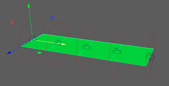
The number of spans of the surface does not correspond to the number of controllers.

In our example, 3 controllers should be sufficient for the first layer. In this exercise, we will create 3 levels of deformation, which will give us a lot of control.
The placement of the controllers should not be random because they need to align exactly with the spans of your surface. To determine where to place them, you first need to rebuild your surface to achieve the correct number of spans.
To know which parameters to use for rebuilding our surface, it's straightforward:
-
Number of spans V: Always set this to 0.
-
Number of spans U: Set this to the number of controllers you want (in our example, 3), minus 1, so 2.
-
Degree V: Set to 1 (linear) because we want deformation only along the length of the surface.
-
Degree U: This depends on the type of deformation you want. Use 3 for smooth or 1 for sharp.
In our situation, we will rebuild it like this:
(Do not forget to delete the history after rebuilding the surface.)

From there, we can place the controllers much more easily. To do this, simply display the CVs (control vertices) of the surface and snap the controllers to these CVs. This ensures that the controllers are in the correct positions.

Next, here we will choose how many ribbons we want to have. In our case, we will go with 6 ribbons. So, we will create 6 additional controllers, preferably with a different shape than the first controllers to avoid confusion.

3. Node graph connection
Now we need to create a system that allows us to snap the ribbons onto the surface. This way, whenever we move the surface, the ribbon controllers will maintain the correct orientation and be placed correctly.
To achieve this, we will use a matrix system and primarily utilize another node called pointOnSurfaceInfo. This node will compute a point and its rotation relative to the surface normal.
By using the U and V parameters as inputs, we can specify where on the surface we want the point to be located.


The slight issue with the pointOnSurfaceInfo node is that it doesn't directly provide translation and rotation outputs. This can be restrictive when positioning our elements. However, we can convert its outputs into a matrix, which will greatly assist us.
To achieve this, we'll use a node called "fourByFourMatrix". This node allows us to transform the information provided by the "pointOnSurfaceInfo" into a matrix format. After doing this, we can then transfer this matrix to our ribbons.
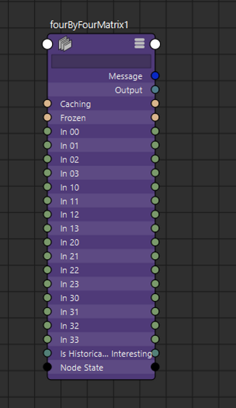

This process allows you to structure and create your own matrix, where each entry in the matrix is defined by your parameters. This gives you the ability to customize your matrices and perform various operations.
For those unfamiliar with matrices, don't worry the connections will be straightforward and nothing will be complex.
To give you a general idea, here is how this node is decomposed and what it looks like from a matrix perspective.


With this color code, I'll be able to explain more visually how I'm going to connect the two nodes together. For the connection, we'll use the attributes Position, normalized normal, normalized tangent U, and normalized tangent V.
These attributes will return the vectors of the matrix and its position. With all of this, we'll be able to determine the point's location on the surface and its orientation.
If we translate what the attributes of the "PointOnSurfaceInfo" node provide:
-
The attribute position returns the translation of the matrix,
-
The attribute normalized normal returns the Vector X,
-
The attribute normalized tangent U returns the vector Y,
-
The attribute normalized tangent V returns the vector Z.

Once we understand this, all that's left is to connect the branches like this

For the next step, you will need a "multMatrix" and a "decomposeMatrix". This will allow you to extract the rotation and position data from each "fourByFourMatrix". Without this, we risk having shear and incorrect values.
Here’s how to proceed:
-
Connect the output of the "fourByFourMatrix" to the first input of the "multMatrix".
-
Then, take the "parentInverseMatrix" of your ribbon controller and connect it to the second input of the "multMatrix."
This setup ensures that you have all the exact data about your point on the surface, enabling you to create the perfect position. This will ensure that, in all situations, your ribbon points are correctly positioned.
-
Finally, connect the output of your "multMatrix" to your "decomposeMatrix", and link the rotation and translation to your ribbon controller.
Here’s what it looks like in the video. (Make sure to set the translation and rotation to zero for your ribbon controllers.)

Well done, you've just completed setting up your first ribbon controller. Now, the less enjoyable part will be doing the same for each subsequent ribbon controller. You'll need to replicate the same connections for each one, which can be quite tedious and time-consuming, but you'll get it perfect in the end.
After connecting all the elements, you'll need to set up each "PointOnSurfaceInfo" node by configuring the U and V coordinates. For the V coordinate, it will always be 0.5 for each surface, as we want it to be in the center of the surface. Then, for the U coordinates, you'll need to evenly distribute each ribbon across the surface.
To distribute the controllers evenly, calculate the distance between each ribbon. This involves dividing 1 by the number of ribbon controllers minus 1 (in our case, 6 minus 1 equals 5).
So, we calculate: 1 / (6 - 1) = 0.2, where 1 represents the total length of the U coordinates.
Once we have this distance, we multiply it by the ribbon number:
-
For the 1st ribbon controller, the U parameter will be: 0.2 * 0 = 0.0
-
For the 2nd ribbon controller, the U parameter will be: 0.2 * 1 = 0.2
-
For the 3rd ribbon controller, the U parameter will be: 0.2 * 2 = 0.4
-
For the 4th ribbon controller, the U parameter will be: 0.2 * 3 = 0.6
-
For the 5th ribbon controller, the U parameter will be: 0.2 * 4 = 0.8
-
For the 6th ribbon controller, the U parameter will be: 0.2 * 5 = 1.0

Once you've done this, you've created your ribbon system. Now, if you skin your surface with the first controllers you created (with influence set to 1), your ribbon controllers will follow the surface movements seamlessly.

There you have it, with this, we've created our ribbon system. You can replicate multiple layers like this; there's nothing stopping you from creating another surface that could be skinned with the ribbons. Then, you could create ribbons of ribbons to add yet another level of deformation. In our case, we don't need to do this as we already have four levels of deformation.
4. How to skin
Skinning the surface won't be complicated at all. Since we've ensured that there are as many controllers as there are spans on the curve, each span will simply need one influence corresponding to its joint.

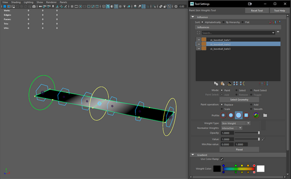

Once you've done this, the next step is to skin the bat. To do this, you'll use the joints from the ribbons. This will allow you to achieve all the deformations you want using this system. Set a maximum of three influences per joint. Smooth the entire bat to achieve a very linear skinning between all the joints for the smoothest deformation possible.
Please note: If you chose to skin the surface in Sharp mode, you'll also need to set your ribbons to Sharp mode for consistent deformation.

For the sake of this tutorial, we've decided to use only 6 ribbons to simplify understanding of the system. However, currently, with few joints skinned to the bat, the deformations aren't perfect for maximizing deformation while retaining volume. I recommend creating a second layer using these 6 ribbons, with at least 15 to 20 ribbons in this second layer. This will provide better deformations and more control over the shape.
To create the new layer, it's straightforward. We'll recreate a surface, rebuilding it based on the 6 ribbons we've already created, which means we'll have 5 spans to set in the surface rebuild.

All that's left is to create, for each controller, the system that allows you to attach the controller to the surface using the "PointOnSurfaceInfo" and "fourByFourMatrix" nodes. Then, skin the new surface to the first ribbon, and afterward, skin the ribbons from Layer 2 to the bat.
From there, you'll have multiple levels of deformation, allowing you to control all the visual aspects that the bat could take on and let your imagination shape it into various forms.

5. Implementation system for IK/FK
This kind of system is extremely practical when it comes to creating characters, as it allows you to design limbs that are highly flexible and malleable. It enables smooth deformations and emphasizes dynamic curves, enhancing customization possibilities in your rig and enabling animators to produce higher-quality animations.
To demonstrate how to implement this in a character, we'll reuse the rig we created together in the course "How to Rig a Body Character." In that course, we developed a system for the arm with 3 hierarchies: one for the system, another for IK, and a third intermediate arm for switching between FK and IK. This setup facilitated the IK-FK switch.
Together, we'll create and integrate this system into the arms so that we can deform and bend our limbs effectively.

To begin, we'll need to place the surfaces as we did at the beginning of this tutorial. These surfaces will allow us to then position all the ribbons and everything else we'll need later on. For each limb, we'll need to place two surfaces.
In this tutorial, we'll use the example of the arm to explain the system. The first surface will start from the shoulder and end at the elbow, while the second surface will start at the elbow and end at the wrist.
(To place the surfaces correctly, you can create surfaces with a degree of 1. This will give you only 4 points on the surface, making it simpler to position. Then, you just need to snap each side of the surface to the controllers or joints that already exist.)

Be careful: if you scale the surfaces or apply rotations, remember to freeze their transformations. This precaution prevents scaling issues or pivot-related problems. It's advisable to freeze transformations and reset the pivot to the center of the world afterward.

Once the surfaces are positioned, transformations are frozen, and the pivot is zeroed out, we can proceed to reduce the surfaces. In our example, as shown at the beginning of the tutorial, we will use 3 controllers to skin the surface. These 3 controllers will be driven by our FK and IK chains. This setup allows the FK or IK chains to first move the three controllers, which in turn deform the surface. Then, the surface deformation will affect the ribbons, and finally, these ribbons will be skinned to the mesh.
However, we are not yet at this stage. Knowing that we will use 3 controllers to skin the surface, we will reduce our surfaces to two spans with a degree of 3. (Don't forget to delete history after rebuilding the surfaces.)

Now that we've completed that, we can proceed to create three controllers that will allow us to deform the surface, which we'll refer to as "twist".
We should place one controller at the shoulder, another at the elbow, and for the one in the middle that lies at the midpoint of the surface, you can use a temporary parent constraint to position it exactly in the middle. When placing your controllers, it's crucial that they have the same rotations as the controllers and joints of the arm, so I recommend using the match transform tool. (As I mentioned in the "How to Rig a Body Character" course, it's essential to have exactly the same rotations for both the IK and FK systems and the intermediate arm so that the intermediate arm can switch smoothly between FK and IK modes without rotation issues.)
I recommend using the match transform tool on the joints:
"Shoudler_L", "Elbow_L", "Wrist_L".
These three joints make up the intermediate arm.


Once these 3 controllers are placed, do the same for the forearm by placing 3 more controllers using the match transform method.

Once we have done this, we can now skin the joints of the twist controllers with their corresponding surfaces. This will allow us to deform the surfaces using the controllers and subsequently bend the arms.

Before placing the ribbons on the surface and establishing all connections to ensure the ribbons follow the surface correctly, we need to create a few groups to control the light blue controllers.
To do this, we'll follow a similar approach used in the previous course on the intermediate arm joints "Shoulder_L", "Elbow_L", and "Wrist_L".
Remember, in the previous course, we used pairBlend nodes to switch between IK and FK and connected translations and rotations to the joints. This allowed us to smoothly interpolate between them. Similarly, in this scenario, we'll use the groups "root_twist_Shoulder_L" and "root_twist_Elbow_Bot_arm_L" to replace "Shoulder_L" and "Elbow_L" joints. After that, we'll create a few parent constraints to ensure everything works correctly.
Let's proceed step by step. First, we'll use the "root_twist_Shoulder_L" and "root_twist_Elbow_Bot_arm_L" groups and remove the connections from the "Shoulder_L" and "Elbow_L" joints, then reconnect them to the two controllers "root_twist_Shoulder_L" and "root_twist_Elbow_Bot_arm_L". This way, these groups will now control the movements instead of the joints themselves.

In essence, this process isn't entirely new because it mirrors what we covered in the previous course. However, instead of connecting to joints directly, you're connecting to groups.
Please ensure that in the "Root..." group's offset parent matrix, you apply the world inverse matrix of its parent group, if applicable.From here, remember to reset the arm positions to their default to avoid any offset issues. Then, you'll need to create a few constraints and groups that will allow the surfaces to move correctly based on the arm's position.
Firstly, for the forearm, you'll need to create a point constraint for the "twist_Wrist_L" controller to the "Wrist_L" joint. To do this, create a group above the "c_twist_Wrist_L" group named "cstr_twist_Wrist_L". Then, proceed with setting up the point constraint.

Once you have applied the point constraint on the "cstr_twist_Wrist_L" group you created, the next step is to set up an orient constraint on the same group. This orient constraint will use the "root_twist_Elbow_Bot_arm_L" group as its target. This setup ensures that the orientations match, aligning the direction of the controller with that of the arm.

Next, for the last controller, "twist_middle_Bot_arm_L", you'll first need to create a parent group for the "c_twist_middle_Bot_arm_L" group, which we'll call "cstr_twist_middle_Bot_arm_L". Then, we'll apply a parent constraint on this "cstr_twist_middle_Bot_arm_L" group, referencing the two groups "root_twist_Elbow_Bot_arm_L" and "cstr_twist_Wrist_L"
This will allow the forearm to perfectly follow the arm as it should behave normally.

For the upper arm, we will do almost the same thing. We will need to create constraints on the controller "twist_Elbow_Top_arm_L" and the controller "twist_middle_Top_arm_L".
First, we have created parent groups for the groups "c_twist_Elbow_Top_arm_L" and "c_twist_middle_Top_arm_L", which we will call "cstr_twist_Elbow_Top_arm_L" and "cstr_twist_middle_Top_arm_L". Next, we will create a point constraint on the group "cstr_twist_Elbow_Top_arm_L", using "root_twist_Elbow_Bot_arm_L" as the reference.

Next, we will create an orient constraint on the group "cstr_twist_Elbow_Top_arm_L", using "root_twist_Shoulder_L" as the reference.

And finally, as we did with the group "cstr_twist_middle_Bot_arm_L", we will also create a parent constraint on the group "cstr_twist_middle_Top_arm_L", using "root_twist_Shoulder_L" and "cstr_twist_Elbow_Top_arm_L" as the references.
From there, your surfaces will perfectly follow your arm, allowing you to move it in any direction while the surfaces maintain their position accordingly.

To make your surfaces more linear and reduce the cubic function appearance.
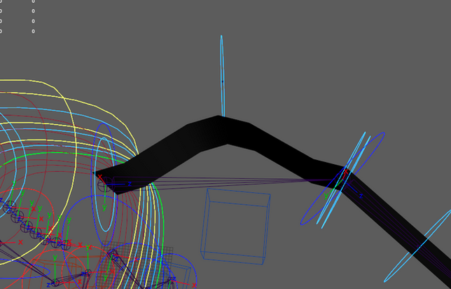
ou can slightly smooth the skin of the CVs that are between the spans; this will give your surface a more linear appearance.

Once you've done this, all that's left is to place the ribbons on the surface and create all the connections for each ribbon and each surface. (This step can be very time-consuming depending on the number of ribbons you place. If you're comfortable with scripting, I recommend creating a script that automates these connections with a click.)

It remains only one more step to make this perfect. The only issue we encounter now is when we rotate the wrist or the forearm. The problem here is that in reality, when we rotate our wrist, the entire forearm also rotates increasingly. Similarly, when we rotate our forearm, the entire upper arm rotates as well. So, we need to create this system.
In theory, this is not complicated. For example, to achieve this for the wrist, we would rotate it on the Z-axis by a certain degree. Then, we would rotate the controller in the middle of the forearm by half of the degree on the Z-axis of the wrist. This way, we could replicate the same principle as in real life when we rotate our wrist.


To do this, we'll need to create a system that decomposes the wrist movement rotations to isolate only the rotations on the Z-axis.We can't use a simple orient constraint for this because it tends to bug out when constrained to a single axis; it's not designed for this type of situation.
But we can work around this issue by using an aim constraint and a point constraint limited on two axes. To implement this technique, we'll need to create three locators and one group. The principle of this method involves using a locator as a target, which will be parent constrained to the hand. A second locator will decompose the position of this target locator to remove the translation along the Z-axis based on the position and orientation of the hand. The third locator will allow us to create an aim constraint on the locator that decomposes the position of the first locator. This way, the locator with the aim constraint will have rotations only on the Z-axis, and this rotation will be corrected to follow any situation accurately.
First, we will create a group called "hook_twist_Wrist_L" and link it by matrix with the group "cstr_twist_Wrist_L". Then, we will create three locators: "loc_decompose_Z_Wrist_arm_L", "loc_target_Wrist_arm_L", and "loc_aim_Z_Wrist_arm_L".

Next, to begin, we need to create an offset between the center of the group and the locator "loc_target_Wrist_arm_L" by a small distance along the X or Y axis, as you prefer. For this tutorial, we will choose the Y axis.

From there, we can create our parent constraint on the group "loc_target_Wrist_arm_L", referencing the joint "Wrist_L". Make sure to enable "Maintain Offset" for this constraint.

Once this is done, all you have to do is create a point constraint on the locator "loc_decompose_Z_Wrist_arm_L", with the reference being the locator "loc_target_Wrist_arm_L". In the constraint settings, make sure to disable "Maintain Offset" and constrain only the X and Y axes.
This technique will allow you to restrict the locator "loc_decompose_Z_Wrist_arm_L" to move only around the group "cstr_twist_Wrist_L". It's similar to flattening the rotation onto a 2D plane, which will later help us to extract the rotation we need.

To finish, we need to create an aim constraint on the locator "loc_aim_Z_Wrist_arm_L", with the reference being the locator "loc_decompose_Z_Wrist_arm_L". Set the Object Rotation Up Vector of the aim constraint to be the group "hook_twist_Wrist_L". This will constrain the rotations of the aim constraint to a single axis, which is the Z-axis, allowing us to simply retrieve the Z-axis rotation of the locator and copy it to our wrist twist control.

Once this is done, we need to create two parent groups for the groups "c_twist_middle_Bot_arm_L" and "c_twist_Wrist_L". We will replace the prefix "c_" with "axisZ_". These groups will allow us to rotate exclusively around the Z-axis to avoid cycle issues. Unfortunately, we don't have much choice in this matter unless we opt for more complex systems to reduce the number of groups.
After creating these groups, the next step is to perform the Z-axis rotation within these groups. Remember to halve the rotations for the group "axisZ_twist_middle_Bot_arm_L".

After completing this, the next step is to replicate the same process for the shoulder. This step is identical to the wrist, except instead of connecting the "hook..." group with a matrix, we'll use a simple parent constraint stringed with the "c_clavicle_L" group.
In this case, instead of wanting to rotate around the Z-axis, we aim to freeze the Z-axis rotation. Therefore, we simply need to multiply the Z-axis rotation by -1.

Once this step is completed, clean up by organizing the groups as you see fit, for example, placing all surfaces in a group named "SURFACE", all locators in a group named "LOCS", etc.
The joints "Shoulder_L" and "Elbow_L" will no longer be useful, so you can delete them. When deleting them, it's crucial to ensure the following for the "Wrist_L" joint:
-
Set the offset parent matrix to 0 in translation and rotation.
-
Reset the joint orientation to zero.
This maintenance ensures that your rig remains clean and functional after removing unnecessary components.


Now, all that's left is to select all the joints of your ribbons, add them to the skin of your character, perform skin painting, and you're done!

With this system in place, you now have the ability to deform the arms in any movement or situation you desire. You can stress your arms and deform them as needed, all thanks to the ribbon system.
You can take it further by creating systems that modify certain attributes on the surfaces, such as parameters that move the different ribbons on the surfaces. You could also develop a system that deforms upon contact with a collider, or explore more advanced systems that allow for even greater customization of your rig.
I hope this lesson has served you well !

